Search

100% Secure delivery without contacting the courier
Need help? +91-81444-11468

In Stock

AutoCAD 2D

AUTOCAD 2D software can be used to draft designs more quickly and with greater precision, without using stencils and technical drawing instruments. It also allows users to document and annotate drawings with text, dimensions, leaders and tables.  You can access a comprehensive set of editing, design, annotation tools and work faster in an intuitive user interface.

AutoCAD started as a design tool for engineers and architects, but is now used by other professionals as well. Autodesk, the company behind AutoCAD, has developed custom versions that can be used by design engineers, civil engineers, electrical and electronics engineers and mechanical engineers. AutoCAD thus covers a vast canvas from engineering to industrial sector, there is an AutoCAD package for everyone.

What will you learn
  • You can understand the AutoCAD workspace and user interface.
  • You will learn how to use basic drawing, editing, and viewing tools.
  • You can organize drawing objects on layers.
  • You can add text, hatching, and dimensions

499

Syllabus

Chapter: 1 INTRODUCTION

File management,

User interface,

Basic settings,

Navigation bar,

Steering wheel,

View port


Chapter: 2

NEW FEATURES Go to start,

Close other Over kill,

Dim edit

Chapter: 3

DRAW SETTING & CONDITION

Units, Limits,

UCS icon Function keys & its work


Chapter: 4

DRAWING TOOLS:

Line, polyline, Circle,

Arc Rectangle, polygon Ellipse,

Elliptical arc, spline Spline Edit,

Xline, Ray, Points Measure,

Divide, Region Wipeout,

Helix, Donut, Revision cloud,

hatch, Gradient


Chapter: 5

MODIFY TOOLS:

Move, copy, Rotate,

Scale Stretch, fillet,

Chamfer Erase, offset,

Explode Array, polar Array,

Path array Trim, extend,

Mirror, Edit polyline, Edit spline,

Edit hatch Edit array, break,

Break at point Blend vertex,

Joint, overkill, lengthen.


Chapter: 6

Annotations Dimensions

Dimension setting Linear dimension,

Aligned dimension Angular dimensions, arc length,

Radius Diameter, ordinates,

Jogged Base line dimension,

Dim base Continuous dimension


MULTILEADER:

Multileader setting, create multileader,

Multileader edit, multileader align

TEXT:

Text style, single text, multi text

TABLE:

Table style, create table Table Edit, text placement


Chapter: 7

PROPERTIES TOOLS

Property: color, line type Line weight,

Show icon Match properties

GROUP: New group, Edit group Active and inactive group


Chapter: 8

LAYERS

Create layers, Edit layers

properties Layer control (hide, freeze, lock Layout lock, print lock)


Chapter: 9

UTILITIES TOOLS

UT tools – distance, Radius,

Angle Area, volume, quick select,

Quick calculator, point, ID point

CLIP BOARD: copy, cut, paste Paste as a block, paste special


Chapter: 10

BLOCK AND ATTRIBUTES BLOCK:

create block (Block & write block) Insert block, block Editor

ATTRIBUTES:

create attributes, Attributes mode setting,

Block Attributes, insert attributes,

Edit attributes Tool palettes,

Design Centre,

Add object to Tool Palettes and Design Centre,

Insert object from Tool Palettes and Design Centre


Chapter: 11

CONSTRAINTS GEOMETRIC CONSTRAINT

Coincident, parallel, tangent Collinear, mid-point,

Smooth Concentric, Horizontal, symmetric Lock,

Vertical, Equal, Show and hide constraints

DIMENSION CONSTRAINT:

Linear, aligned, Radius, diameter Angle,

Show and hide dim constraints Delete constraints, parameters


Chapter: 12

References:

External reference, Attach files

IMPORT:

Import 2D, import 3D,

OLE LAYOUTS:

Multi view, paper space, model space Page setup,

Print setup Print setting, PDF conversion DXF, batch print


Chapter: 13   CIVIL PROJECT


Chapter: 14   MECHANICAL PROJECT

Duration

10 Hrs

Language

தமிழ்

Qty

1 DVD ROM

Reviews

There are no reviews yet.

Write a review

Bestsellers

Categories:

Solidworks

499
(0 Reviews)
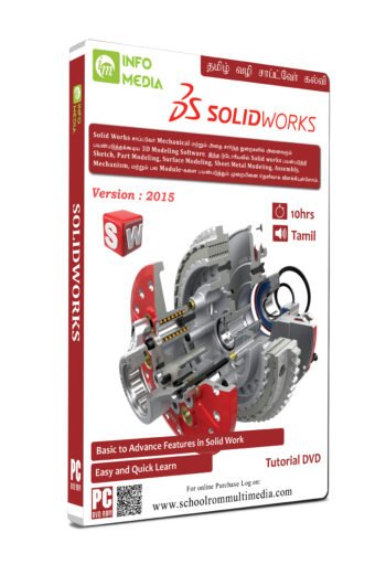
Description SolidWorks is a solid modeler, which utilizes a parametric feature-based approach to create models and assemblies. The software is written on Parasolid -kernel. It lets the designers quickly sketch out ideas, experiment with features and dimensions, and produce models and detailed drawings. This course describes the concepts and terminology used throughout the SOLIDWORKS application.  The model created by SolidWorks consists of 3D geometry, which defines its edges, faces, and surfaces. This software makes you to design models quickly and precisely.  When you design a model using SOLIDWORKS, you can visualize it in 3D, the way the model exists once it is manufactured.

Revit MEP

499
(0 Reviews)
Description MEP stands for mechanical, electrical, and plumbing which are the three engineering disciplines that are addressed by Revit MEP. This software is powerful tool to leverage dynamic information in intelligent models. It is used to simplify the engineering design process, making product design and development more professional. This course covers the techniques for achieving better coordination between disciplines (mechanical, electrical, and plumbing) and making the most out of Revit MEP software. This course has been designed to teach the concepts and principles of creating 3D parametric models of MEP system from engineering design through construction documentation. This course is intended to introduce learners to the software’s user interface and electrical, and piping/plumbing components that make the Autodesk Revit software a powerful and flexible engineering modeling tool.
Categories:

Revit Architecture

499
(0 Reviews)
Description Revit is BIM software widely used by architects, engineers, and contractors to create a unified model that all disciplines and trades can use to complete their work. Revit hosts the information that forms the model from which drawings and documents are derived. It allows architects and other building professionals to design and document a building by creating a parametric three-dimensional model which includes both the geometry and non-geometric design and construction information. It is used to coordinate all data inputs (including CAD) and produce federated project deliverables.
Categories:

Google SketchUp Pro

499
(0 Reviews)
Description SketchUp enables the most intuitive way to design, document and communicate your ideas in 3D. You can work smart and work fast with SketchUp’s objects. It's a fast and easy 3D modeling for anything you can imagine.

AutoCAD 3D

499
(0 Reviews)
AutoCAD 3D is a powerful tool to create 3D objects, like architectural floor plans and constructions or engineering projects. The need for 3D is a necessary part of the designing world. Without it, the design almost looks like a sketch. Moreover, 3D is a boost for all the interior designers, architects who can design life-like models of any building, office or any exterior with some interiors as well like furniture, walls, show pieces and more. Using 3D models, users can get a more evocative design and they can even see the virtual images of their projects. In a 3D design, the user gets to know the physical dimensions of the objects and its distance in relation with other objects in the total layout. This feature helps enormously to see and modify arrangements of objects based on their sizes.
Categories:

NX CAD

499
(0 Reviews)
Description NX CAD software is an integrated and advanced Computer-Aided Design, Computer-Aided Engineering, and Computer-Aided Manufacturing solutions. This software is an integrated product design solution which streamlines and increases product development process to deliver innovative product in a collaborative environment. It works effortlessly with other CAD systems and has the potential to deal with complex products. NX CAD design tools are a breakthrough in the industry, setting new standards for speed performance and ease of use.
Categories:

CNC-VMC

499
(0 Reviews)
Description VMC is the most economical and most effective way of processing metals and other substances. VMCs are easy to use compared to HMC and easier to configure and manage. The VMC debugger is easier, which is why it is widely used on the market. VMC is more versatile compared to horizontal counterparts and has relatively simple CNC control. Most VMC machines have three axes, x axis, y axis and z axis. The axis means the number of motors that can be individually driven to control the position of the tool. The X axis is usually left to right, the Y axis is pointing forward, and the Z axis is pointing up and down. In the standard 3-axis VMC, the cutter remains in the vertical direction. the cutting head in this milling machine is vertical and is a special type of milling machine in which the spindle moves in a vertical axis called the z axis. It has simpler configuration, management and functionality.

Back to Top
Product has been added to your cart